
pkiller
Joined 8 years ago
Karma
1,199
Submissions
36
Member since
Oct 9
Joined 8 years ago
This was a personal project to make a custom video game console in this case using an FPGA, a couple of years back I finished one using microcontrollers and an actual CPU.
This project uses just enough SRAM and external components and a just enough powerful FPGA to be a retro-styled video game console. I wanted to learn how to use FGPAs and continue to learn how video game consoles worked while building something unique.
So in a way, in terms of the technology, they're similar, except of course a Mister is something a lot more useful, I would say, as it simulates "real devices" and has a huge game library and this is just an educational project.
Well, I think it isn't that hard to get an analog video signal going. Having a TV that took an RGB analog signal, meant that I could connect the microcontroller directly to the TV (using resistors to convert the voltage and for the color DAC).
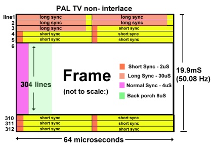
Then all I did was get the timing right, especially with the sync signal. Along with other resources, I used this image ( http://martin.hinner.info/vga/pal_tv_diagram_non_interlace.j... ) to understand when to set the Sync signal to 0 or to 1. When using a microcontroller you can use interrupts or you can have well-timed instructions to set the sync signal on or off at the correct time, I chose the latter. The micros I used are AVR 8-bit architecture based, so most instructions always take 1 cycle, others take from 2 to 4 cycles to execute, simply by looking up in the manual I could calculate when certain instructions would execute and build a program in assembly that would generate the sync signal successfully. And if everything was right, my TV picture would switch to black, meaning it detected a valid PAL signal.
Of course, it wasn't always this easy, for example, I had a bug when I started, I wasn't setting one of the registers correctly and it took me a day to solve it, I had to look at the code over and over until I figured out what was wrong. Not having an oscilloscope nor a logic analyzer certainly made it harder.
Another lucky thing for me, was that the TV I have (an old CRT TV) is actually quite forgiving and even if I don't feed the timings exactly, it will still show a picture, so that helped.
Once I had a valid signal going I tested sending pixels to the screen, and I did use patterns to see if I had the timing right for each pixel, if I took too long switching pixels they would get wide. So I tried some checker patterns and stuff like that, but nothing fancy. I hope this answers your question. It really isn't that difficult to generate a video signal and also I was quite lucky to get it working early on.
I probably didn't do things like they should be done, but it worked for me. I would say that best thing is have a logic analyzer or oscilloscope to check if the signal you're generating corresponds to what it should be, that makes it a lot easier.
Actually they are still being manufactured to this day, that's one thing I didn't mention in the blog post is that you can get a brand new Zilog Z80 today, the 6502 (the CMOS version, 65C02) is also available. You can probably get them from all the major electronic components stores (Digikey, Mouser, etc).
Answering your question, well, even thought this is an electronics engineering project, I don't feel qualified to work with electronics professionally, for example, there's a lot of knowledge I lack. I do work as a software engineer and I have done a couple of interviews myself to hire people and I do believe this helps when applying to a job, I'm not saying it completely replaces your qualifications but it might at least give you an edge. I'm seeing this as someone who would want to hire someone skillful. A technical project certainly is on the very least a nice thing to have in a CV. Of course this is just my opinion. And if you are feeling like applying for a job based on your projects, just give it a go.
One advice I can give is: if you do have projects of your own, big or small, don't do it like me and keep them to yourself for years :P. I really had no idea so many people would appreciate my pet project.
But yeah, they also had less colors to work with and palettes (which were costier to implement in a software renderer). And this CPU is also faster than of those consoles. I did give myself a more confortable system in terms of RAM and computational power.
But my aim was for a machine that would sit somewhere between the 3rd and 4th generation.
The double buffering I understand as well, if I was working with an FPGA I would not have gone with frame buffers, for sure, but that was the solution I found at the time using the components I was using and it worked.
The attention this has gotten, especially here in HN is still a bit unbelievable to me (and amazing of course). I don't want people to think this is an optimal console design or anything. This is by no means a perfect project or "the way to go" in terms of homebrew video game consoles, it's just the way I found to do one while learning electronics along the way.
And thanks :)
I'm sorry the hardware and code were stolen.
And of course it's always worth reviewing, I got inspiration out of projects just like that and besides my code is a mess too, don't worry about that.
I am proud and honestly reading all these comments of people like you saying awesome stuff and also saying this inspires them makes me even prouder :)
I am considering doing a series of blog posts, I don't know how often I could write them or if I could keep them going, but I will try. I'm not big in social media and I have never written any posts or anything like before this one, which is weird, I'll admit it, so all this is kind of new, but I think I'll give it go.
Old systems used line-buffers like the Neo Geo or no buffers like the NES, for example. So yeah, going with a frame-buffered approach was definitely easier, but this was not the only reason I chose this way. I had a lot of restrictions, I was learning a lot of stuff, I didn't know how to work with FPGAs and I stuck with DIP package ICs that I could put on breadboards and experiment. And that's why I picked the AVR microcontrollers, which are awesome but have their disavantages. They have good performance (20Mhz), but not many pins and I had to bit-bang things like external RAM access (actually the PPU accesses 3 RAMs with only 32 IO pins available), which meant that it takes "some time" to access external memory. That's why I chose 2 microcontrollers for video instead of just one, one of them could take "all the time in the world" (one frame) to fetch information and write a frame to the frame buffer while the other would generate the video signal and dump the a frame to the TV. Connecting the two, I felt a double buffer was better.
I definitely would have preferred doing a more "traditional" non-buffered render system, but this was the solution I found with what I had to work with.
I hope serves as a good explanation and maybe I'll get to explain these details better in another post :).
I'm gonna try and keep posting.
I would love to learn more and be able to work with faster circuits like you. Yes it's way easier to work with "slow" digital circuits I had very little issues using breadboards and really long wires, that probably look cringy to you and others.
I'm actually a bit overwhelmed with all the comments and I'm trying to answer at least a few of them.
Just wanted to say that, even without knowing you, I think you could absolutely be a tinkerer or creator, just choose something you would like to build, start small and go from there. :)